
Manual for Installation
of Voice over the Internet Protocol (VoIP)
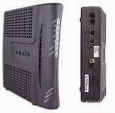
Arris TM502G Phone/EMTA Modem.
Introduction
The following manual can be used to set up “VoIP” in each of
the following system: ATT VoIP, Xfinity VoIP. Also, it could be used in any
type of device that uses the technology (Voice over Internet Protocol) and has
a phone line available. The installation requires a medium level of expertise
and understanding of telephone wiring to complete this task.
Warning:
Failure to follow each of the steps; might result in an
unsuccessful activation of your phone service. In the case of alarm set up, it
could result in the creation of an isolation network where you alarm system is
completely disconnected from the telephone network.
What is VoIP?
VOIP is an acronym of the phone service identified as “Voice
over Internet Protocol”. (Communications technology for carrying voice
telephone traffic over data network such as the Internet. VoIP uses the Internet
Protocol (IP)-one half of the Transmission Control Protocol (TCP/IP), a global
addressing system for sending and receiving packets of data over the Internet.
VoIP works by converting sound into a digital signal, which is then sent over
a data network such as the Internet. The conversion is done by a device, such
as a personal computer (PC) or special VoIP phone, that has a high-speed, or
broadband, Internet connection. The digital signal is routed through the
network to its destination, where a second VoIP device converts the signal back to
sound. Because of the digital nature of VoIP, call
quality is normally much higher than that of a standard telephone. Another
advantage is that VoIP frequently costs less than standard
telephone and long-distance service.) VoIP. (2014). In Encyclopaedia Britannica
What is EMTA?
EMTA is an acronym to the term “Embedded Multimedia Terminal
Adapter”. This is a combination of cable modem and telephone adapter.
Glossary of Terms:
The following types of wires are currently found in old and
new constructions and their proper identification is necessary to properly
connect them:
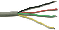
Cat3: Heavily used in the 90’s for wiring homes and offices.
As a result it is still present in old homes.
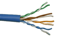
Cat5: Their usage commenced around the year 2000. It is the
standard cable used in offices and homes.

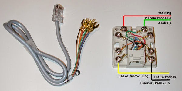
Illustration of how to connect cat5 to cat3.

NID: Acronym for “Network Interface Device”. It is always
located next to your power line meter equipment.

Scotch lock (use to connect and splice phone wires).

Network Interface Device (also referred to as EBM by technicians).
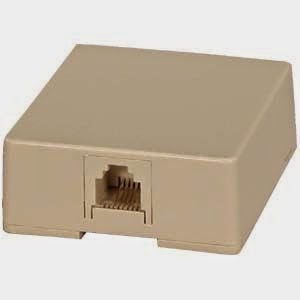
RJ11 Modular Single Port Surface Mount Jack.
List of required
tools/equipment:
·
EMTA (embedded multimedia terminal adapter) Modem
with line1 for dial tone services
·
1 Box Cat-5e
·
1 3M scotch lock hand crimping tool with step
jaws and long nose /crimping pliers
·
1 Wire striper
·
1 Flat #1 screw driver
·
1 Phillip #1 screw driver
·
1 Professional scissors for wires
·
Tone generator line tracer tester tone with
amplifier probe kit
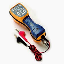
·
But-set and a modular adapter
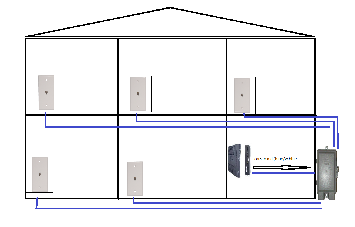
Fig 1 Homerun feed (preferred inside wiring (IW) phone
network connection)
Instructions:
·
Connect the EMTA to the signal and power up.
·
Wait for all the light to be on, wait for line 1
to be on.
·
Plug the but-set on line1 located behind the
EMTA.

·
Check and wait for the dial tone behind the EMTA
or gateway
·
Activate dial tone by calling the IVR 1-800
number.
·
Check dial tone with your but set. (If no dial
tone; continue to troubleshooting guide).
·
Run test by calling in/out from the EMTA or
gateway.
·
If test went successfully continue with the
following step below.
·
Here you can have two different ways to finish
the installation (simple telephone network installation: base phone set
straight connect to the EMTA and its station base around the house) or
(advanced network: following the procedure that will continue next).
·
Run a cat5 wire from the room located the EMTA to
the NID.
·
If no phone jack present. Install an rj11 jack
and connect the blue wire to the new jack.

·
Connect the new jack to the EMTA using an RJ11
Modular Telephone cable.
·
Go to the NID and disconnect the NID from
external cable (ASW) to isolate the phone network only to the inside network.
(Fig 3 y 4)
·
Disconnect the ASW from the EBM and use the wire
from the EBM (green /red) to connect to the cat5 (blue and white blue) refer to
fig 6.
·
Connect all jacks that you wish to activate to
the EBM (EBM hold up to four lines) Fig 4. For more lines to be activated
follow the tutorial of “how to splice and connect IW using schlock “refer to
fig 5.
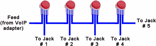
(Fig 5) Proper procedure of how to splice a jack to a single
feed.
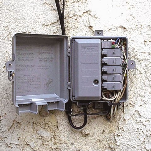
(Fig 2) Inside wires connected to the NID.
(Fig 3) ASW identification.

(Fig 4) ASW identification and proper cut.

(Fig 6) Identification of most common part inside the NID.
·
Connect the test phone in each phone jack and check
for dial tone.
·
Run test by calling in/out for each phone
number.
·
While calling, listen for static, noise in the
line, delay in the call, gap in the voice, dropping call, or ring too low or
almost impossible to hear. (If one of these problem appear on the phone
service. Refer to troubleshooting guide technician to aim for a better
resolution).
(Problems of interference and
attenuation
Two-wire copper circuits did not solve all
the problems of long-distance telephony, however. As the number of lines grew,
interference (or cross talk) from adjacent lines on the same crossarm of
telephone pole became significant. It was found that transposing the wires by
twisting them at specified intervals canceled the cross talk. ) telephone. (2014). In Encyclopaedia Britannica.
If alarm is
present. Follow next steps
Today’s technology makes it easy for a non-expert to do the
installation. Leader Security Companies are now using GSM Modules that connect
their systems to cellular antennas to communicate with cell towers over
wireless networks such as our cellular phones. That makes it a very independent
system capable of receiving updates, proper calibration and call for emergency services;
this type of technology does not need a landline as it used to need in the past.
Also, it has a very reliable connectivity that is worth of its price (fig 7). However,
there are cases when the expert is needed to proper wired an old alarm system.

(Fig 7) GSM Module for Alarm System (it eliminates the need
of a land-line requirements)
Old system alarm work with plain line telephone service and
they need to receive a dial tone in order to communicate with the emergency
system such as 911 or police department.
So, this is our job. Make sure the alarm system has dial
tone after a successful VoIP installation. This job is normally done by an
alarm technician who has previously run the cable and leaves everything connected
and working. In the other hand after we take over from another phone provider,
we as technicians have to guarantee that all services remain as we found them
before our visit. Additionally, it is very important to know the compatibility
of this alarm with our new phone service. And further questions are needed to properly
proceed with our installation.
Instructions for
Wiring an Alarm Panel with VoIP.
·
Identify the wire that goes to the alarm panel
by a tone/searching method. If no wiring existing or bad wire preexist. Follow
the guide to proper wire the alarm panel.
·
Create a back feed this way (send dial tone to
the rj31x using the cat3 green/red wires or the cat5 blue/white blue wires).
·
Connect to the tips 4 and 5 in the rj31x
matching the picture below.
·
Take the second pair of wires to return the dial
tone back to the NID.
·
Connect the following color black/yellow
from the cat3 or orange/white orange from the cat5 to the tips 1
and 8 from the rj31x. Refer to fig 7, 8, and 11

(Fig 11) Proper Connection for Medical Alert Monitoring
System
Additional
Components
RJ31X

(Fig 8) Proper Wiring
for the Distribution rj31x

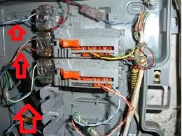
(Fig 9) Alarm Panel

(Fig 11) cat5 connected to the rj31x
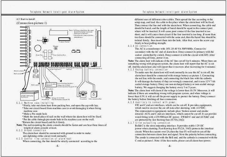
(Fig 10) Telephone Network Alarm System
The cat5 blue is the new wire that runs from the NID to the
alarm panel were blue and orange wires are connected to 4-5 and 1-8 refer to
fig 12
.jpg)
(Fig 12) pins 1-8
AutoChessInc©
Reviewed December 2014 ©
THIS INFORMATIVE MANUAL IS FOR SHARING OVER THE INTERNET;BUT REMEMBER TO INCLUDE THE AUTHOR PAGE AND THIS BACK LINK AS REFERENCE AND TO RESPECT THE PUBLISHER HONOR FOR HIS JOB
Reference:
VoIP. (2014). In Encyclopaedia Britannica. Retrieved from http://academic.eb.com/EBchecked/topic/1017653/VoIP
telephone. (2014). In Encyclopaedia Britannica.
Retrieved from http://academic.eb.com/EBchecked/topic/585993/telephone
The content is quite good. For VoIP installation you can use CallHippo's services. It may help you in finding the right VoIP provider for your business.
ReplyDelete